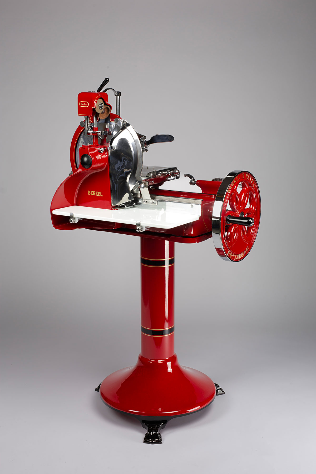
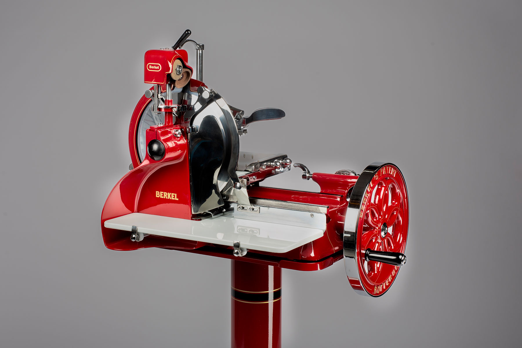
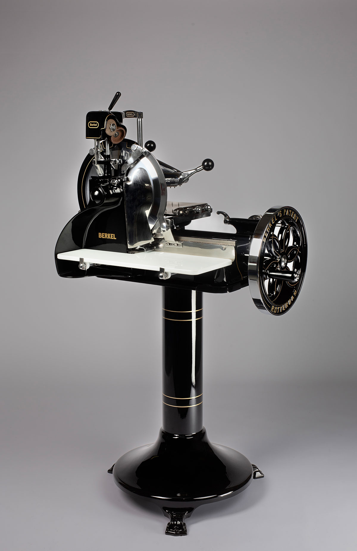
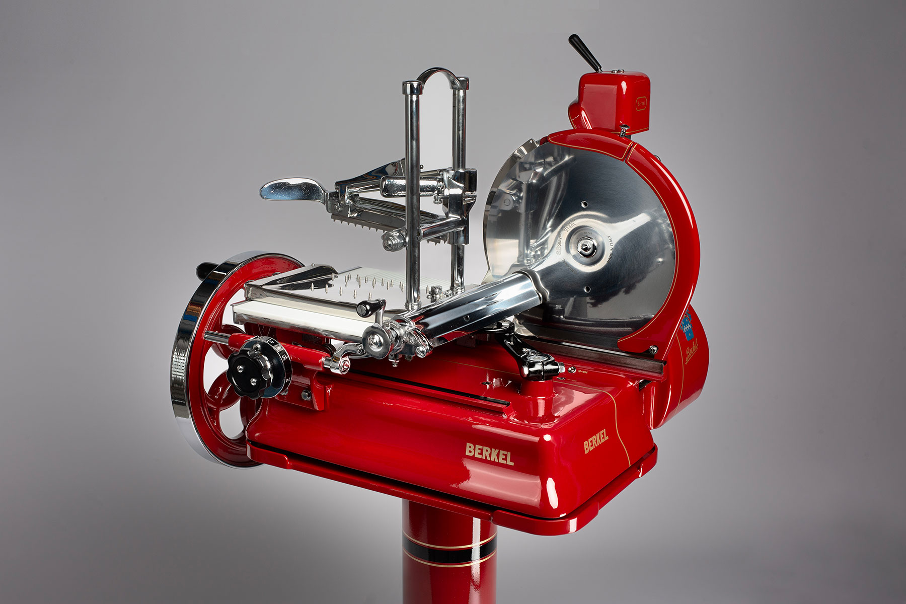
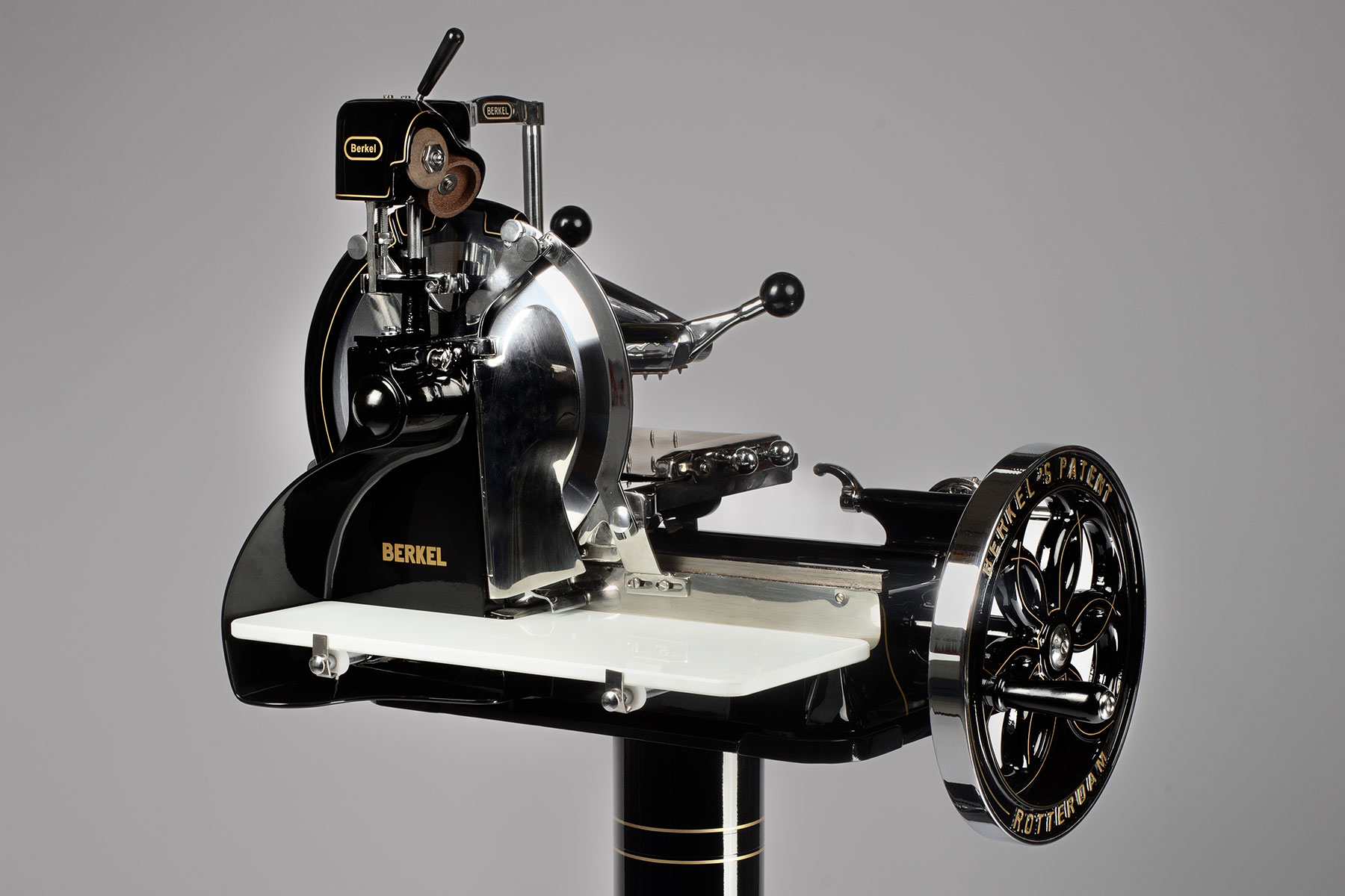
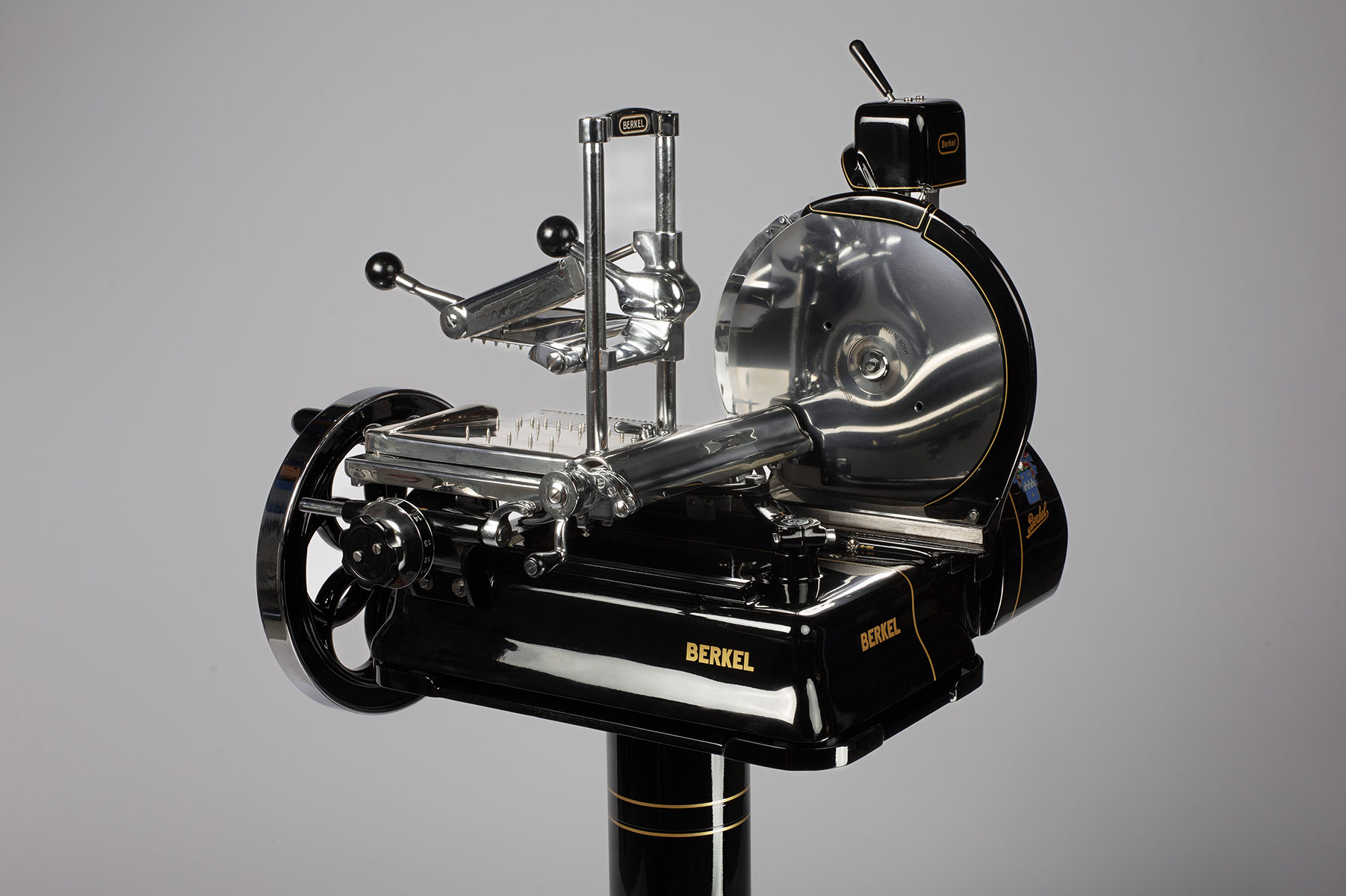
Flywheel slicer Berkel model 10
Model:
Berkel 10
Color:
Black / Cream / Red
Production:
1936 – 1969
Technical data:
Blade: 319
Width: 610
Depth: 830
Height: 600
HISTORICAL NOTES
The Berkel flywheel slicer model 10 with pedestal was realized starting from 1936 and had been distributed since 1969. The model in question is a flywheel slicer with contained dimensions having nothing to envy from the most sophisticated models in terms of mechanics and slicing effectiveness. The slicing synchronism of Berkel model 10 is similar to the previous models 5 and 7. Some parts instead were improved and optimized at the point that Berkel decided to use them ‘till the 60s during all the successive production.
The worm screw and the straight ribbed comb were substituted by the conical screw. The comb doubles the contact surface and it’s no longer assembled onto the fixing clamp, but on a telescope scrolling headframe. It is even inserted in the worm screw at a very high coupling charge. Such device together with the conical coupling, compensates the comb wear and allows to obtain the best efficiency and life length of such professional slicer. Upon the headframe a pin pokes out where the clamp is inserted and blocked in.
The worm screw and the headframe are covered with a shaped carter, unlike the previous manual slicer models in which they were immediately visible. It’s about a closed and smooth flywheel slicer.
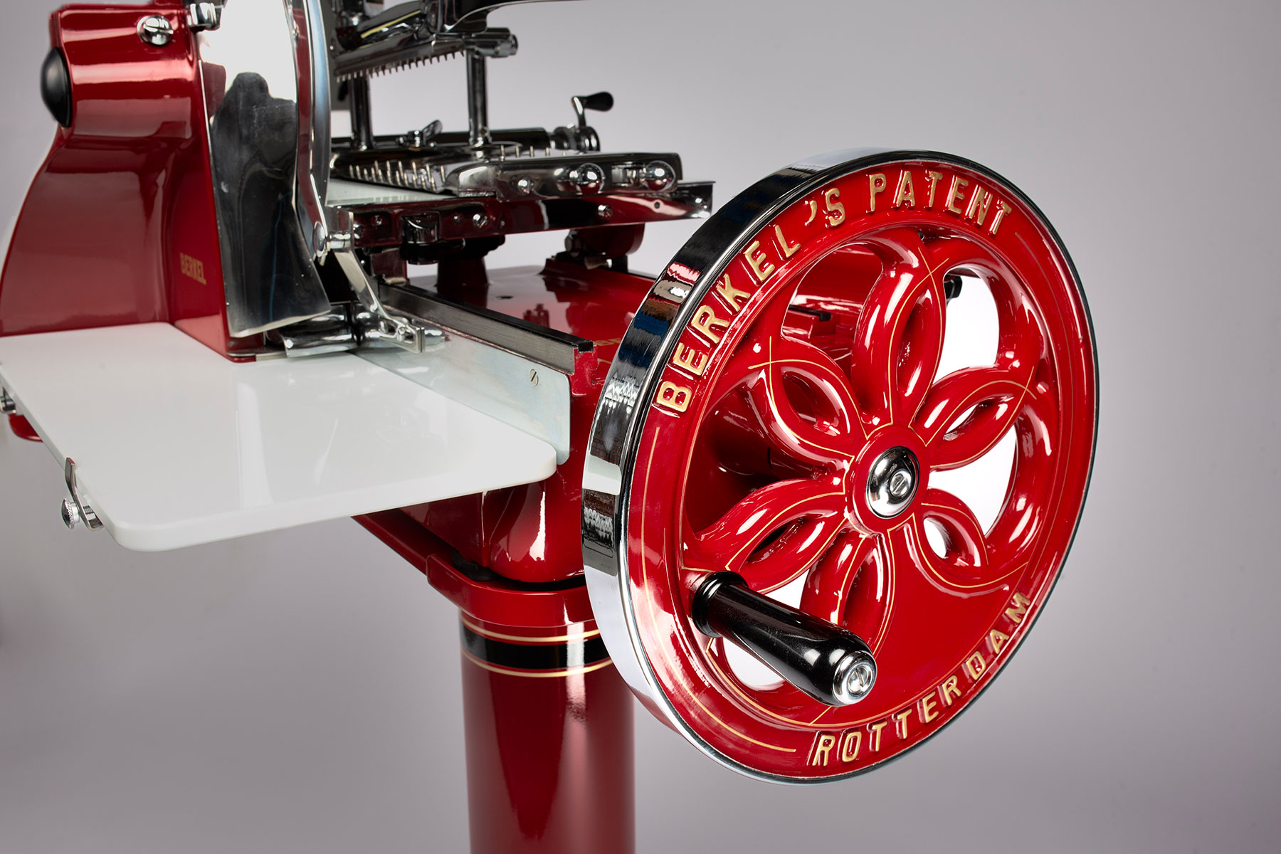
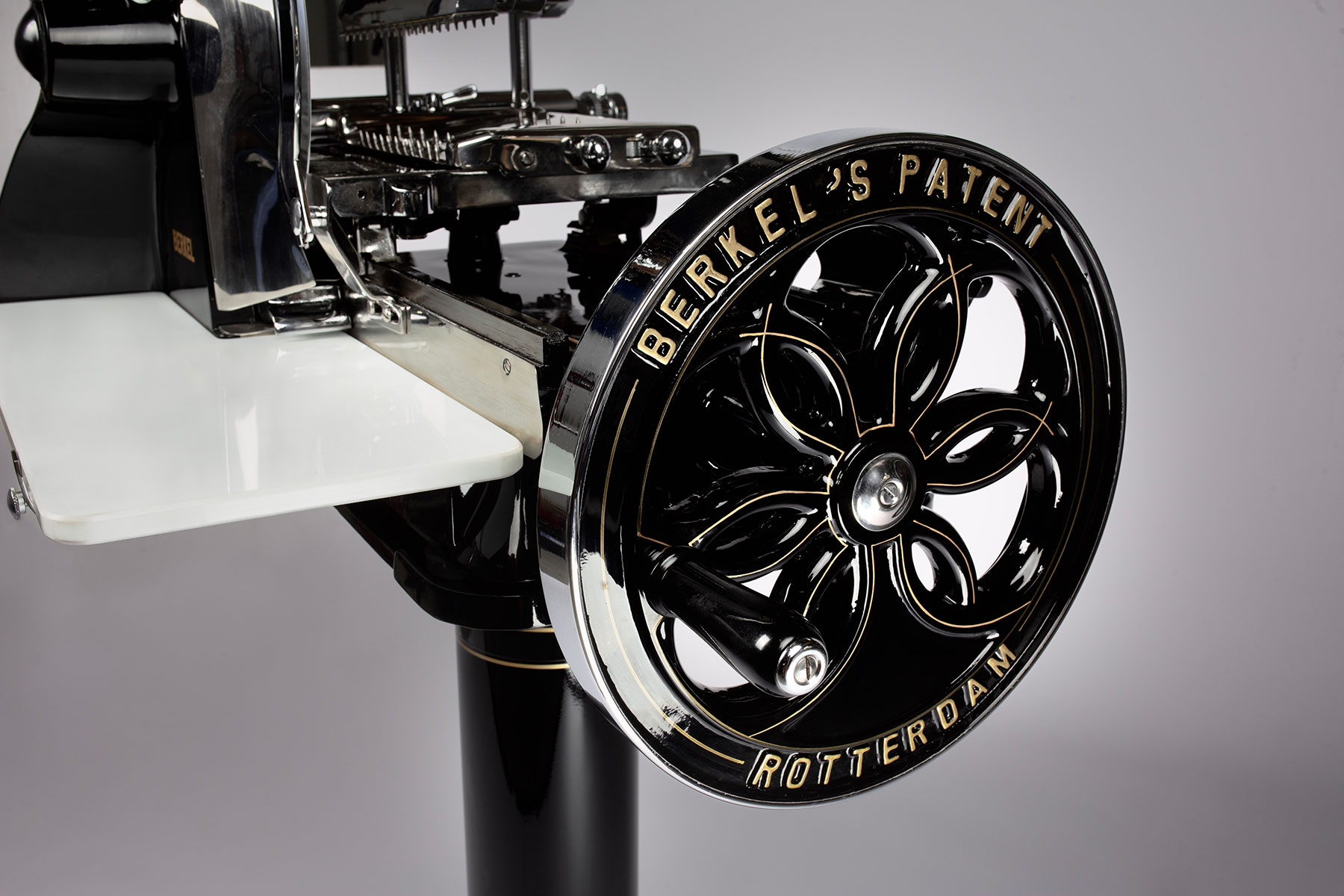
The flywheel operates the gears assembly placed at the machine base, which generate the blade movement – by means of a chain – and the scroll carriage – through two connecting rods.
This professional slicer has a 319mm diameter blade. The scroll carriage, then moves on guided wheel by a binary present at the machine base.
On the base of such flywheel slicer is the graduated knob for the slice thickness regulation which operates a peck-shaped lever in axle to the cog wheel situated on the carriage. By rotating, the cog wheel will convey its movement to the worm screw where the comb telescope headframe is inserted, which being hooked to the clamp will generate the slicing movement. In this hand operated slicer is a lever linked to the cog wheel which, once operated in the two directions, it will move the clamp to the desired position, right or left. The hub supporting the blade of slicer Berkel model 10 is fixed in the machine shoulder, which is flattened performing a winged-shape bow at its external side. This allow the machine tray to extend and gain more working surface on using the slicer. This is a slicer with a closed sharpener with a painted crown. To move the two stones for sharpening, it is necessary to operate the lever acting on the cam.

